
DLP & ILP Systems
.png)
DLP SYSTEMS

ILP DUAL AGENT SYSTEMS
-
AutoFireX® Systems are Pre-Engineered, self-contained, Reliable, and cost-effective Automatic Fire Detection & Suppression units for single or multiple enclosures/spaces/equipment(s) against Fires.
-
Multiple Detection points for Faster -Detection & Suppression of fire in seconds, thereby mitigating loss due to equipment damage and downtime.
-
Easy to install in any new or existing Equipment (Electrical Panels, server rack, etc.) and requires no power to operate.
-
AutoFireX® Systems are Environmentally Friendly – Low-Pressure systems utilizing UL certified Clean Agents & come with various interface options to initiate activities like Annunciation, trip Power input supply, ventilation, interface, and monitoring through BMS, SCADA, etc.
DIRECT LOW PRESSURE - DLP CLEAN AGENT FK5-1-12 SYSTEM UNIT
PRODUCT DESCRIPTION & PRINCIPLE OF OPERATION
AutoFireX® DLP- Direct Low-Pressure Clean Agent Systems are primarily Pre-Engineered Automatic Fire detection and suppression Systems utilizing various Low-pressure Clean agents like HFC227ea, FK 5-1-12, FE36. These units are designed, manufactured, and tested in ISO 9001:2015 certified facilities.
The AutoFireX® Linear Pneumatic Fire Detection Tubing (LP-FDT) is installed and connected to DLP Valve via dual seal threaded union attached to the isolation ball valve and routed throughout the protected hazard area/enclosure. Being heat sensitive, the primary function of the Linear Pneumatic Fire Detection Tube (under pressure) is to detect heat/fire and activate the valve for discharge of the agent by rupturing at the hottest point along its installed length on flame impingement. On rupture, a nozzle is formed at the bursting point.

TYPICAL ILLUSTRATION DLP SYSTEM
Due to loss of the pressure in the tube, the clean agent under pressure, in the cylinder then flows out through the tube and discharged out at burst point/nozzle, extinguishing the fire instantly and flooding the protected enclosure, which helps in preventing reignition.
Each DLP system consists of a High-Grade Stainless-Steel Direct valve with integrated pressure gauge adaptor with Schrader valve on the valve body to monitor cylinder pressure, and a quarter-turn isolation valve to interface with the AutoFireX® Fire Detection Tubing., and a PRD (Pressure Relief Device) tested up to 44Bar is also provided. The system is supplied complete with CE Cylinders and Brackets Stainless steel siphon tube with appropriate agents, as required.
To assist in annunciation, an optional pressure switch provided, can be installed at one of the ports on the valve or at the end of the detection line using End of Line Adaptor, also available with the system. The pressure switch provides a potential free contact, that can be interfaced, with the existing FACP (Fire Alarm Control Panel) to indicate system discharge, shutdown ventilation, shut-off electrical power, as may be required. Alternatively, it can also be connected to an Audio Visual (A/V) alarm unit for annunciation.
TECHNICAL SPECIFICATION
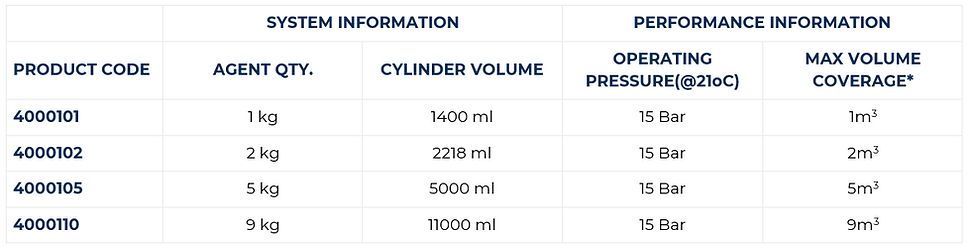
*Figures based on ideal conditions in fully enclosed space. Actual figures may vary according to application.
Maximum volume coverage is determined by agent concentration discharged within the enclosure where the fire hazard is located. The discharge time for the DLP system utilizing various agents differs from agent to agent and the capacity of the cylinder.
INDIRECT LOW PRESSURE - ILP SYSTEM UNIT
PRODUCT DESCRIPTION & PRINCIPLE OF OPERATION
AutoFireX® ILP- Indirect Low-Pressure Clean Agent Systems are primarily Pre-Engineered Automatic Fire detection and suppression System utilizing various Low-pressure agents like ABC Dry Chemical Powder, Foam, Clean agents (HFC227ea, FK 5-1-12, FE36). These units are designed, manufactured, and tested in ISO 9001:2015 certified facilities
The AutoFireX Linear Pneumatic Fire Detection Tubing (FDT) is installed and connected to ILP Valve via dual seal threaded union attached to the isolation ball valve and routed over/near the protected hazard area/enclosure. Being heat sensitive, the primary function of the Linear Pneumatic Fire Detection Tube (under pressure) is to detect heat/fire and activate the valve for discharge of the agent by rupturing at the hottest point along its installed length on flame impingement. On rupture due to loss of pressure in the tube connected to the valve, the pressure from the top head assembly of the ILP valve is released (this can also be achieved by manual activation via operating manual release) thereby initiating the internal piston to open position, allowing the pressurized agent to travel through any or combination of three outlet ports via delivery hose/pipes and discharge out from the fixed nozzles, within the protected area, flooding the entire area with the agent and suppressing the fire instantly.

TYPICAL ILLUSTRATION ILP SYSTEM
Each ILP system consists of a High-Grade Stainless-Steel Indirect valve with three standard detections 1/8” ports (SV, P/s or P/g, etc.), and three 3/8” discharge ports, SS siphon tube, integrated pressure gauge embedded in the valve body for extra protection to monitor cylinder pressure, and a quarter-turn isolation valve with provision to interface with the AutoFireX Fire Detection Tubing, a PRD (Pressure Relief Device) tested to 44Bar is also provided. The system is supplied complete with CE Cylinders and Brackets with appropriate agents, as required.
To assist in annunciation, an optional pressure switch can be installed at one of the ports on the valve or at the end of the detection line using an End of Line Adaptor, also available with the system. The pressure switch provides a potential free contact, that can be interfaced, with the existing FACP (Fire Alarm Control Panel) to indicate system discharge, shutdown ventilation, shut-off electrical power, as may be required. Alternatively, it can also be connected to an Audio Visual (A/V) alarm unit for annunciation.
As the system is Pre- Engineered (refer to our Design Installation manual), therefore, when the discharge piping and nozzles are installed within the limitations stated in the manual no complex hydraulic calculations are required to determine pressure drop, agent flow, or discharge time, etc.
TECHNICAL SPECIFICATION

*Figures based on ideal conditions in fully enclosed space. Actual figures may vary according to application.
Maximum volume coverage is determined by agent concentration discharged within the enclosure where the fire hazard is located. The discharge time for the DLP system utilizing various agents differs from agent to agent and the capacity of the cylinder.